Case study · Jan – Jul 2025
High-speed STOL UAV
I led the mechanical design of a carbon-fibre UAV built for short takeoff and landing, taking it from SolidWorks models and structural and aerodynamic analysis to fabricated, assembled hardware.
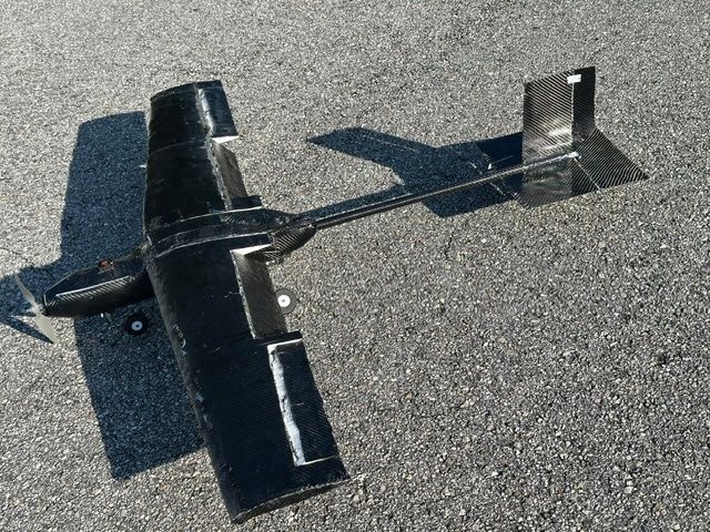
- Propeller
- Pod fuselage
- High-mounted wing
- Trailing-edge control surfaces
- Carbon tail boom
- Empennage
- Lighter airframe, with required safety factors heldDesign result from analysis
- 12%
- SolidWorks parts, assemblies and GD&T fabrication drawings
- 40+
Objective
Design a composite fixed-wing UAV for short takeoff and landing, with high speed as a design goal, and carry it from concept through fabricated hardware to prototype assembly and flight testing.
Constraints
- The airframe had to get lighter without dropping below its required safety factors.
- A composite structure and a retractable landing-gear mechanism both had to be integrated into the same airframe.
My role
I led the mechanical design. That meant owning the CAD, drawing release and manufacturability decisions from concept to fabricated parts, and running the structural and aerodynamic analysis that drove design changes.
Prototype assembly and flight testing were team efforts across a five-person multidisciplinary group; I supported both, and wrote bills of materials and technical documentation for the build.
Approach
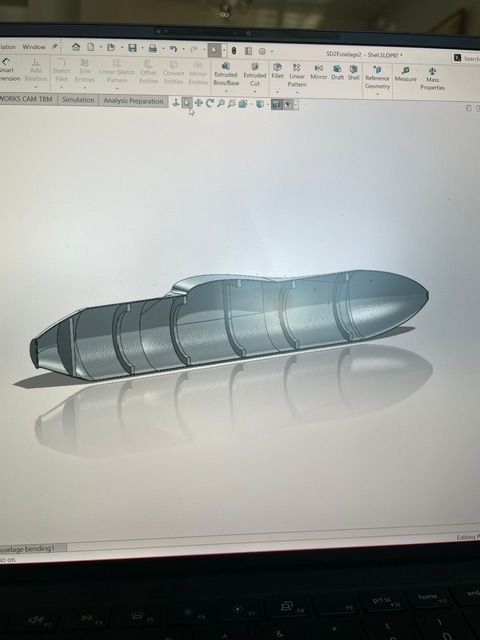
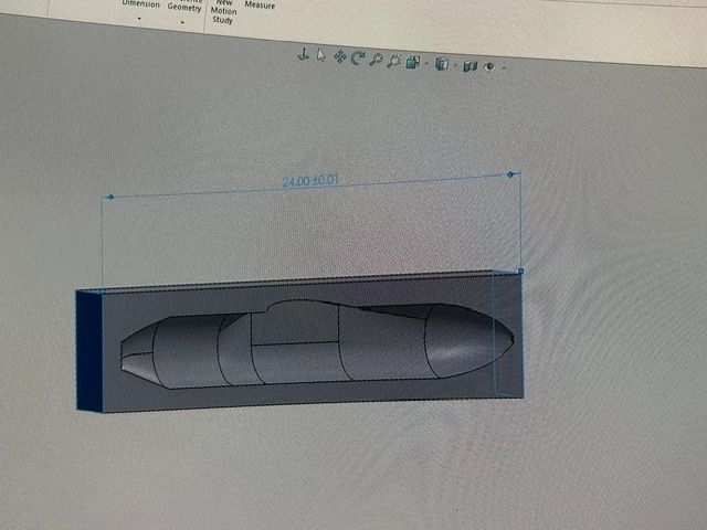
The fuselage was developed in SolidWorks as a lofted body and then shelled, leaving a thin skin supported by internal ring bulkheads. A mould block was modelled around the fuselage profile for the composite parts. In total I produced more than 40 parts, assemblies and GD&T-annotated fabrication drawings.
Testing and analysis
- Aerodynamics. Lift and drag were evaluated in XFLR5 using NACA 0012 (symmetric) and NACA 4412 (cambered) sections.
- Structure. Structural FEA in SolidWorks Simulation checked stress against the required safety factors at each design iteration.
Outcomes
- The FEA-driven iterations reduced airframe weight by 12% while holding the required safety factors. This is a design result from analysis, not a measured flight-test figure.
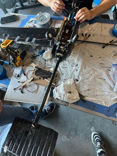
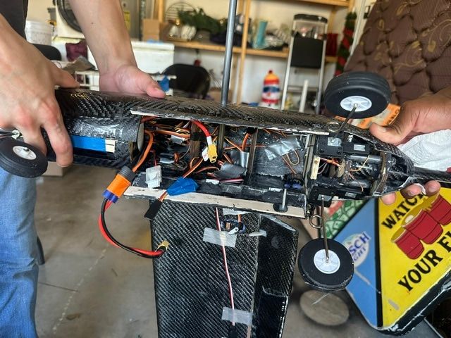
- The released drawings took the design through to fabricated, assembled hardware, shown in the photographs on this page.